
Arduino UNO R4 WIFI board based Plant Watering System | 52Pi Plant Watering System
The 52Pi Plant Watering System, based on an Arduino UNO R4 WiFi board, is a smart irrigation system that automatically waters plants. It uses sensors to monitor soil moisture and triggers a pump when needed, all controlled via WiFi for remote monitoring and adjustments.
SCIENCE PROJECTS
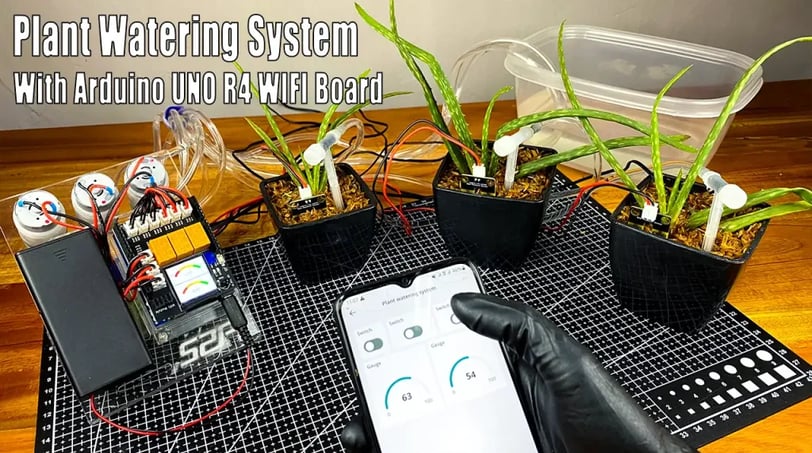
The 52Pi Plant Watering System leverages the capabilities of an Arduino UNO R4 WiFi board to create a sophisticated automated irrigation solution. This system offers precise control and monitoring of plant watering needs through a comprehensive kit. Three soil moisture sensors provide granular data on soil hydration levels, while three NTC temperature sensors offer crucial environmental context. Three independently controlled water pumps ensure targeted watering, precisely delivering water as needed based on sensor readings. A central control module simplifies integration with the Arduino board, and a 1.3-inch IPS RGB TFT screen displays real-time sensor data and system status for convenient local monitoring. For remote control and management, the system incorporates an IR receiver compatible with a standard IR remote, along with WiFi connectivity enabling integration with cloud platforms like Arduino Cloud and Blynk, or custom web server solutions. This allows users to monitor plant health and adjust watering schedules from anywhere with internet access, receiving alerts when attention is required.
component
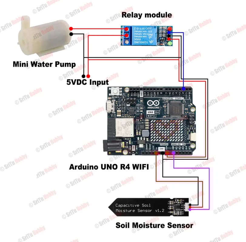
* Arduino UNO R4 WiFi board
* Three Soil Moisture Sensors
* Three NTC Temperature Sensors
* Three Water Pumps
* Control Module
* 1.3-inch IPS RGB TFT Screen
* IR Receiver
* IR Remote (for remote control)
Now, connect the Arduino board to the computer. Then, copy and paste the following program to the Arduino IDE.
* Arduino UNO R4 WiFi board
* Three Soil Moisture Sensors
* Three NTC Temperature Sensors
* Three Water Pumps
* Control Module
* 1.3-inch IPS RGB TFT Screen
* IR Receiver
* IR Remote (for remote control)
The downloads for the Arduino program, libraries (vector, IRremote, Math, TFT eWidget, TFT eSPI) are not hardware components and thus have been omitted.
#include <Math.h> // import Math library #include <vector> // import vector library #include <string.h> #include <IRremote.h> // IR remote header file #include <Arduino.h> #include "PinDefinitionsAndMore.h" #include <IRremote.hpp> // include the library #include <TFT_eSPI.h> // Hardware-specific library #include <TFT_eWidget.h> // Widget library #define HUMI3 A0 #define HUMI2 A1 #define HUMI1 A2 #define TEMP3 A3 #define TEMP2 A4 #define TEMP1 A5 #define water_pump_1 2 #define water_pump_2 3 #define water_pump_3 4 #define IR_RECEIVE_PIN 5 #define DECODE_NEC #define Green_LED 6 #define Red_LED 7 // create instance of TFT display TFT_eSPI tft = TFT_eSPI(); // define meters rh1 - moisture_1 , rh2 - moisture_2 MeterWidget rh1 = MeterWidget(&tft); MeterWidget rh2 = MeterWidget(&tft); int count = 3; // Initialize a global variable 'count' to 3. int channel = 0; // Initialize a global variable 'channel' to 0. const int flag = 3; // Define a constant 'flag' with a value of 3, representing the number of channels. // setting a structure to store tempvalue and index information struct TempValue { int value; size_t index; }; // here stored the temp_table of the temperatue -> resistor table and it has been convert to ADC reading range from 0-1023. // check the table of NTC 10K resister table and convert it to adc reading range by following formula // resister number / (resister number + 10000.0) // for example: when temperatrue is 25 degree, the NTC's resistor number is 10000.0 ohm, so the adc number will be: // 10000.0 / (10000.0 + 10000.0) = 512, so, if you reading from adc and get 512 +/- 10 equals 25 degree. // dut to the NTC dose not a linear component, so you need to check the table to grab the temperature value. std::vector<int> temp_table = { 994, 992, 990, 988, 986, 983, 981, 978, 975, 972, 969, 966, 962, 959, 955, 951, 947, 943, 938, 933, 928, 923, 918, 912, 907, 901, 894, 888, 881, 874, 867, 860, 852, 845, 837, 828, 820, 811, 802, 793, 784, 774, 765, 755, 745, 735, 724, 714, 703, 692, 682, 671, 659, 648, 637, 626, 614, 603, 592, 580, 569, 557, 546, 535, 523, 512, 501, 490, 479, 468, 457, 446, 436, 425, 415, 405, 395, 385, 375, 365, 356, 347, 338, 329, 320, 311, 303, 295, 287, 279, 271, 264, 256, 249, 242, 235, 229, 222, 216, 210, 204, 198, 193, 187, 182, 176, 172, 167, 162, 157, 153, 148, 144, 140, 136, 132, 128, 125, 121, 118, 114, 111, 108, 105, 102, 99, 96, 94, 91, 88, 86, 84, 81, 79, 77, 75, 73, 71, 69, 67, 65, 63, 62, 60, 58, 57, 55, 54, 52, 51, 50, 48, 47, 46, 45, 44, 43, 41, 40, 39, 38, 37, 36, 36, 35, 34, 33, 32, 31, 31, 30, 29, 28, 28, 27, 26, 26, 25, 25, 24, 23, 23, 22, 22, 21, 21, 20, 20, 20, 19, 19 }; // customize the abs value int custom_abs(int x) { return (x >= 0) ? x : -x; } // function to check the temp_table by sending adc reading value. TempValue closestNumber(const std::vector<int>& temp_table, int value) { TempValue result; result.value = temp_table[0]; result.index = 0; int min_diff = custom_abs(temp_table[0] - value); for (size_t i = 1; i < temp_table.size(); ++i) { int diff = custom_abs(temp_table[i] - value); if (diff < min_diff) { min_diff = diff; result.value = temp_table[i]; result.index = i; } } result.index -= 40; return result; } void setup() { Serial.begin(115200); // note the baudrate is changed to 115200 // enable IR IrReceiver.begin(IR_RECEIVE_PIN, ENABLE_LED_FEEDBACK); // init tft display and clear screen tft.begin(); tft.setRotation(0); tft.fillScreen(TFT_WHITE); // setting meters parameters for soil moistures rh1.setZones(0, 25, 25, 50, 50, 75, 75, 100); rh1.analogMeter(0, 0, 100.0, "CH1", "DRY", "DRY", "MID", "WET", "WET"); rh2.setZones(0, 25, 25, 50, 50, 75, 75, 100); rh2.analogMeter(0, 120, 100.0, "CH2", "DRY", "DRY", "MID", "WET", "WET"); printActiveIRProtocols(&Serial); pinMode(Green_LED, OUTPUT); pinMode(Red_LED, OUTPUT); pinMode(water_pump_1, OUTPUT); pinMode(water_pump_2, OUTPUT); pinMode(water_pump_3, OUTPUT); } void loop() { float HUMI1_Raw_data = analogRead(HUMI1); float HUMI2_Raw_data = analogRead(HUMI2); float HUMI3_Raw_data = analogRead(HUMI3); float ntc_1_raw_data = analogRead(TEMP1); float ntc_2_raw_data = analogRead(TEMP2); float ntc_3_raw_data = analogRead(TEMP3); TempValue ntc_1_temp = closestNumber(temp_table, ntc_1_raw_data); TempValue ntc_2_temp = closestNumber(temp_table, ntc_2_raw_data); TempValue ntc_3_temp = closestNumber(temp_table, ntc_3_raw_data); rh1.updateNeedle((100 - HUMI1_Raw_data / 10.24), 0); rh2.updateNeedle((100 - HUMI2_Raw_data / 10.24), 0); delay(20); remoteControl(); // Serial.print("Temperature of NTC thermistors:"); // Serial.print("\tNTC1: "); // Serial.print(ntc_1_temp.index); // Serial.print("\tNTC2: "); // Serial.print(ntc_2_temp.index); // Serial.print("\tNTC3: "); // Serial.print(ntc_3_temp.index); // // delay(200); // wait for a while. // Serial.print("Soil Moisture sensor raw data:"); // Serial.print("CH1: "); // Serial.print(HUMI1_Raw_data); // Serial.print("CH2: "); // Serial.print(HUMI2_Raw_data); // Serial.print("CH3: "); // Serial.println(HUMI3_Raw_data); // delay(1000); //wait for a second. } void remoteControl() { if (IrReceiver.decode()) { /* print a summary of received data */ if (IrReceiver.decodedIRData.protocol == UNKNOWN) { Serial.println(F("Received noise or an unknown (or not yet enabled )protocol")); // we have an unknown protocol here, print extend info IrReceiver.printIRResultRawFormatted(&Serial, true); IrReceiver.resume(); // Do it here to preserve raw data for printing with printIRResultRawFormatted() } else { IrReceiver.resume(); IrReceiver.printIRResultShort(&Serial); IrReceiver.printIRSendUsage(&Serial); } Serial.println(); Serial.println(IrReceiver.decodedIRData.command); if (IrReceiver.decodedIRData.command == 0x40 && count % flag == 0) { // press on button on IR controller will generate this data 0x40 digitalWrite(Green_LED, HIGH); // turn on green led count += 1; // add to count variable digitalWrite(water_pump_1, HIGH); // turn on the water pump 1. IrReceiver.resume(); // resume IR digitalWrite(Green_LED, LOW); } else if (IrReceiver.decodedIRData.command == 0x40 && count % flag == 1) { digitalWrite(Green_LED, HIGH); // turn on green led count += 1; // add to count variable digitalWrite(water_pump_2, HIGH); // turn on the water pump 2. IrReceiver.resume(); // resume IR digitalWrite(Green_LED, LOW); } else if (IrReceiver.decodedIRData.command == 0x40 && count % flag == 2) { digitalWrite(Green_LED, HIGH); // turn on green led count += 1; // add to count variable digitalWrite(water_pump_3, HIGH); // turn on the water pump 3. IrReceiver.resume(); // resume IR digitalWrite(Green_LED, LOW); } else if (IrReceiver.decodedIRData.command == 0x19 && count % flag == 1) { digitalWrite(Red_LED, HIGH); // turn off green led count += 1; // add to count variable digitalWrite(water_pump_1, LOW); // turn on the water pump 1. IrReceiver.resume(); digitalWrite(Red_LED, LOW); // turn on red led } else if (IrReceiver.decodedIRData.command == 0x19 && count % flag == 2) { digitalWrite(Red_LED, HIGH); // turn off green led count += 1; // add to count variable digitalWrite(water_pump_2, LOW); // turn on the water pump 1. IrReceiver.resume(); digitalWrite(Red_LED, LOW); // turn on red led } else if (IrReceiver.decodedIRData.command == 0x19 && count % flag == 0) { digitalWrite(Red_LED, HIGH); // turn off green led count += 1; // add to count variable digitalWrite(water_pump_3, LOW); // turn on the water pump 1. IrReceiver.resume(); digitalWrite(Red_LED, LOW); // turn on red led } } }
Now, install the above library files into Arduino IDE. Then, open a new tab and create it as “PinDefinitionsAndMore.h”.
Next, modify the “user_setup.h” file in the TFT_eSPI library. Use the following details for that.
#define ST7789_DRIVER #define TFT_RGB_ORDER TFT_BGR #define TFT_WIDTH 240 #define TFT_HIGHT 240 #define TFT_MOSI 12 #define TFT_MISO 11 #define TFT_SCLK 13 #define TFT_CS 10 #define TFT_DC 9 #define TFT_RST 8 #define SPI_FREQUENCY 27000000 #define SPI_READ_FREQUENCY 20000000 #define SPI_TOUCH_FREQUENCY 2500000
Afterward, copy and paste the following code on this tab.
/* * PinDefinitionsAndMore.h * Contains pin definitions for IRremote examples for various platforms as well as definitions for feedback LED and tone() and includes * Copyright (C) 2021-2023 Armin Joachimsmeyer armin.joachimsmeyer@gmail.com * * This file is part of IRremote https://github.com/Arduino-IRremote/Arduino-IRremote. * Arduino-IRremote is free software: you can redistribute it and/or modify it under the terms of the GNU General Public License as published by the Free Software Foundation, either version 3 of the License, or (at your option) any later version. * This program is distributed in the hope that it will be useful, but WITHOUT ANY WARRANTY; without even the implied warranty of MERCHANTABILITY or FITNESS FOR A PARTICULAR PURPOSE. See the GNU General Public License for more details. * You should have received a copy of the GNU General Public License along with this program. If not, see <http://www.gnu.org/licenses/gpl.html>. * */ /* * Pin mapping table for different platforms * Platform IR input IR output Tone Core/Pin schema -------------------------------------------------------------- DEFAULT/AVR 2 3 4 Arduino ATtinyX5 0|PB0 4|PB4 3|PB3 ATTinyCore ATtiny167 3|PA3 2|PA2 7|PA7 ATTinyCore ATtiny167 9|PA3 8|PA2 5|PA7 Digispark original core ATtiny84 |PB2 |PA4 |PA3 ATTinyCore ATtiny88 3|PD3 4|PD4 9|PB1 ATTinyCore ATtiny3217 18|PA1 19|PA2 20|PA3 MegaTinyCore ATtiny1604 2 3|PA5 % ATtiny816 14|PA1 16|PA3 1|PA5 MegaTinyCore ATtiny1614 8|PA1 10|PA3 1|PA5 MegaTinyCore SAMD21 3 4 5 ESP8266 14|D5 12|D6 % ESP32 15 4 27 ESP32-C3 6 7 10 BluePill PA6 PA7 PA3 APOLLO3 11 12 5 RP2040 3|GPIO15 4|GPIO16 5|GPIO17 / //#define IRMEASURE_TIMING // For debugging purposes. #if defined(__AVR__) #if defined(__AVR_ATtiny25__) || defined(__AVR_ATtiny45__) || defined(__AVR_ATtiny85__) // Digispark board. For use with ATTinyCore. #include "ATtinySerialOut.hpp" // TX is at pin 2 - Available as Arduino library "ATtinySerialOut". Saves 700 bytes program memory and 70 bytes RAM for ATtinyCore. #define IR_RECEIVE_PIN PIN_PB0 #define IR_SEND_PIN PIN_PB4 // Pin 2 is serial output with ATtinySerialOut. Pin 1 is internal LED and Pin3 is USB+ with pullup on Digispark board. #define TONE_PIN PIN_PB3 #define IRTIMING_TEST_PIN PIN_PB3 # elif defined(__AVR_ATtiny87__) || defined(__AVR_ATtiny167__) // Digispark pro board #include "ATtinySerialOut.hpp" // Available as Arduino library "ATtinySerialOut" // For ATtiny167 Pins PB6 and PA3 are usable as interrupt source. # if defined(ARDUINO_AVR_DIGISPARKPRO) // For use with Digispark original core #define IR_RECEIVE_PIN 9 // PA3 - on Digispark board labeled as pin 9 //#define IR_RECEIVE_PIN 14 // PB6 / INT0 is connected to USB+ on DigisparkPro boards #define IR_SEND_PIN 8 // PA2 - on Digispark board labeled as pin 8 #define TONE_PIN 5 // PA7 - on Digispark board labeled as pin 5 #define IRTIMING_TEST_PIN 10 // PA4 # else // For use with ATTinyCore #define IR_RECEIVE_PIN PIN_PA3 // On Digispark board labeled as pin 9 - INT0 is connected to USB+ on DigisparkPro boards #define IR_SEND_PIN PIN_PA2 // On Digispark board labeled as pin 8 #define TONE_PIN PIN_PA7 // On Digispark board labeled as pin 5 # endif # elif defined(__AVR_ATtiny84__) // For use with ATTinyCore #include "ATtinySerialOut.hpp" // Available as Arduino library "ATtinySerialOut". Saves 128 bytes program memory. #define IR_RECEIVE_PIN PIN_PB2 // INT0 #define IR_SEND_PIN PIN_PA4 #define TONE_PIN PIN_PA3 #define IRTIMING_TEST_PIN PIN_PA5 # elif defined(__AVR_ATtiny88__) // MH-ET Tiny88 board. For use with ATTinyCore. #include "ATtinySerialOut.hpp" // Available as Arduino library "ATtinySerialOut". Saves 128 bytes program memory. // Pin 6 is TX, pin 7 is RX #define IR_RECEIVE_PIN PIN_PD3 // 3 - INT1 #define IR_SEND_PIN PIN_PD4 // 4 #define TONE_PIN PIN_PB1 // 9 #define IRTIMING_TEST_PIN PIN_PB0 // 8 # elif defined(__AVR_ATtiny1616__) || defined(__AVR_ATtiny3216__) || defined(__AVR_ATtiny3217__) // For use with megaTinyCore // Tiny Core Dev board // https://www.tindie.com/products/xkimi/tiny-core-16-dev-board-attiny1616/ - Out of Stock // https://www.tindie.com/products/xkimi/tiny-core-32-dev-board-attiny3217/ - Out of Stock #define IR_RECEIVE_PIN PIN_PA1 // use 18 instead of PIN_PA1 for TinyCore32 #define IR_SEND_PIN PIN_PA2 // 19 #define TONE_PIN PIN_PA3 // 20 #define APPLICATION_PIN PIN_PA0 // 0 #undef LED_BUILTIN // No LED available on the TinyCore 32 board, take the one on the programming board which is connected to the DAC output #define LED_BUILTIN PIN_PA6 // use 2 instead of PIN_PA6 for TinyCore32 # elif defined(__AVR_ATtiny816__) // For use with megaTinyCore #define IR_RECEIVE_PIN PIN_PA1 // 14 #define IR_SEND_PIN PIN_PA1 // 16 #define TONE_PIN PIN_PA5 // 1 #define APPLICATION_PIN PIN_PA4 // 0 #undef LED_BUILTIN // No LED available, take the one which is connected to the DAC output #define LED_BUILTIN PIN_PB5 // 4 # elif defined(__AVR_ATtiny1614__) // For use with megaTinyCore #define IR_RECEIVE_PIN PIN_PA1 // 8 #define IR_SEND_PIN PIN_PA3 // 10 #define TONE_PIN PIN_PA5 // 1 #define APPLICATION_PIN PIN_PA4 // 0 # elif defined(__AVR_ATtiny1604__) // For use with megaTinyCore #define IR_RECEIVE_PIN PIN_PA6 // 2 - To be compatible with interrupt example, pin 2 is chosen here. #define IR_SEND_PIN PIN_PA7 // 3 #define APPLICATION_PIN PIN_PB2 // 5 #define tone(...) void() // Define as void, since TCB0_INT_vect is also used by tone() #define noTone(a) void() #define TONE_PIN 42 // Dummy for examples using it # elif defined(__AVR_ATmega1284__) || defined(__AVR_ATmega1284P__) \ || defined(__AVR_ATmega644__) || defined(__AVR_ATmega644P__) \ || defined(__AVR_ATmega324P__) || defined(__AVR_ATmega324A__) \ || defined(__AVR_ATmega324PA__) || defined(__AVR_ATmega164A__) \ || defined(__AVR_ATmega164P__) || defined(__AVR_ATmega32__) \ || defined(__AVR_ATmega16__) || defined(__AVR_ATmega8535__) \ || defined(__AVR_ATmega64__) || defined(__AVR_ATmega128__) \ || defined(__AVR_ATmega1281__) || defined(__AVR_ATmega2561__) \ || defined(__AVR_ATmega8515__) || defined(__AVR_ATmega162__) #define IR_RECEIVE_PIN 2 #define IR_SEND_PIN 13 #define TONE_PIN 4 #define APPLICATION_PIN 5 #define ALTERNATIVE_IR_FEEDBACK_LED_PIN 6 // E.g. used for examples which use LED_BUILDIN for example output. #define IRTIMING_TEST_PIN 7 # else // Default as for ATmega328 like on Uno, Nano, Leonardo, Teensy 2.0 etc. #define IR_RECEIVE_PIN 2 // To be compatible with interrupt example, pin 2 is chosen here. #define IR_SEND_PIN 3 #define TONE_PIN 4 #define APPLICATION_PIN 5 #define ALTERNATIVE_IR_FEEDBACK_LED_PIN 6 // E.g. used for examples which use LED_BUILDIN for example output. #define IRTIMING_TEST_PIN 7 # if defined(ARDUINO_AVR_PROMICRO) // Sparkfun Pro Micro is __AVR_ATmega32U4__ but has different external circuit // We have no built in LED at pin 13 -> reuse RX LED #undef LED_BUILTIN #define LED_BUILTIN LED_BUILTIN_RX # endif # endif // defined(__AVR_ATtiny25__)... #elif defined(ARDUINO_ARCH_RENESAS_UNO) // Uno R4 // To be compatible with Uno R3. #define IR_RECEIVE_PIN 2 #define IR_SEND_PIN 3 #define TONE_PIN 4 #define APPLICATION_PIN 5 #define ALTERNATIVE_IR_FEEDBACK_LED_PIN 6 // E.g. used for examples which use LED_BUILDIN for example output. #define IRTIMING_TEST_PIN 7 #elif defined(ESP8266) #define FEEDBACK_LED_IS_ACTIVE_LOW // The LED on my board (D4) is active LOW #define IR_RECEIVE_PIN 14 // D5 #define IR_SEND_PIN 12 // D6 - D4/pin 2 is internal LED #define IRTIMING_TEST_PIN 2 // D4 #define APPLICATION_PIN 13 // D7 #define tone(...) void() // tone() inhibits receive timer #define noTone(a) void() #define TONE_PIN 42 // Dummy for examples using it #elif defined(CONFIG_IDF_TARGET_ESP32C3) || defined(ARDUINO_ESP32C3_DEV) #define NO_LED_FEEDBACK_CODE // The WS2812 on pin 8 of AI-C3 board crashes if used as receive feedback LED, other I/O pins are working... #define IR_RECEIVE_PIN 6 #define IR_SEND_PIN 7 #define TONE_PIN 10 #define APPLICATION_PIN 18 #elif defined(ESP32) #include <Arduino.h> // tone() is included in ESP32 core since 2.0.2 #if !defined(ESP_ARDUINO_VERSION_VAL) #define ESP_ARDUINO_VERSION_VAL(major, minor, patch) 12345678 #endif #if ESP_ARDUINO_VERSION <= ESP_ARDUINO_VERSION_VAL(2, 0, 2) #define TONE_LEDC_CHANNEL 1 // Using channel 1 makes tone() independent of receiving timer -> No need to stop receiving timer. void tone(uint8_t aPinNumber, unsigned int aFrequency){ ledcAttachPin(aPinNumber, TONE_LEDC_CHANNEL); ledcWriteTone(TONE_LEDC_CHANNEL, aFrequency); } void tone(uint8_t aPinNumber, unsigned int aFrequency, unsigned long aDuration){ ledcAttachPin(aPinNumber, TONE_LEDC_CHANNEL); ledcWriteTone(TONE_LEDC_CHANNEL, aFrequency); delay(aDuration); ledcWriteTone(TONE_LEDC_CHANNEL, 0); } void noTone(uint8_t aPinNumber){ ledcWriteTone(TONE_LEDC_CHANNEL, 0); } #endif // ESP_ARDUINO_VERSION <= ESP_ARDUINO_VERSION_VAL(2, 0, 2) #define IR_RECEIVE_PIN 15 // D15 #define IR_SEND_PIN 4 // D4 #define TONE_PIN 27 // D27 25 & 26 are DAC0 and 1 #define APPLICATION_PIN 16 // RX2 pin #elif defined(ARDUINO_ARCH_STM32) || defined(ARDUINO_ARCH_STM32F1) // BluePill // Timer 3 blocks PA6, PA7, PB0, PB1 for use by Servo or tone() #define IR_RECEIVE_PIN PA6 #define IR_RECEIVE_PIN_STRING "PA6" #define IR_SEND_PIN PA7 #define IR_SEND_PIN_STRING "PA7" #define TONE_PIN PA3 #define IRTIMING_TEST_PIN PA5 #define APPLICATION_PIN PA2 #define APPLICATION_PIN_STRING "PA2" # if defined(ARDUINO_GENERIC_STM32F103C) || defined(ARDUINO_BLUEPILL_F103C8) // BluePill LED is active low #define FEEDBACK_LED_IS_ACTIVE_LOW # endif #elif defined(ARDUINO_ARCH_APOLLO3) // Sparkfun Apollo boards #define IR_RECEIVE_PIN 11 #define IR_SEND_PIN 12 #define TONE_PIN 5 #elif defined(ARDUINO_ARCH_MBED) && defined(ARDUINO_ARCH_MBED_NANO) // Arduino Nano 33 BLE #define IR_RECEIVE_PIN 3 // GPIO15 Start with pin 3 since pin 2|GPIO25 is connected to LED on Pi pico #define IR_SEND_PIN 4 // GPIO16 #define TONE_PIN 5 #define APPLICATION_PIN 6 #define ALTERNATIVE_IR_FEEDBACK_LED_PIN 7 // E.g. used for examples which use LED_BUILDIN for example output. #define IRTIMING_TEST_PIN 8 #elif defined(ARDUINO_ARCH_RP2040) // Arduino Nano Connect, Pi Pico with arduino-pico core https://github.com/earlephilhower/arduino-pico #define IR_RECEIVE_PIN 15 // GPIO15 to be compatible with the Arduino Nano RP2040 Connect (pin3) #define IR_SEND_PIN 16 // GPIO16 #define TONE_PIN 17 #define APPLICATION_PIN 18 #define ALTERNATIVE_IR_FEEDBACK_LED_PIN 19 // E.g. used for examples which use LED_BUILDIN for example output. #define IRTIMING_TEST_PIN 20 // If you program the Nano RP2040 Connect with this core, then you must redefine LED_BUILTIN // and use the external reset with 1 kOhm to ground to enter UF2 mode #undef LED_BUILTIN #define LED_BUILTIN 6 #elif defined(PARTICLE) // !!!UNTESTED!!! #define IR_RECEIVE_PIN A4 #define IR_SEND_PIN A5 // Particle supports multiple pins #define LED_BUILTIN D7 /* 4 times the same (default) layout for easy adaption in the future / #elif defined(TEENSYDUINO) // Teensy 2.0 is handled at default for ATmega328 like on Uno, Nano, Leonardo etc. #define IR_RECEIVE_PIN 2 #define IR_SEND_PIN 3 #define TONE_PIN 4 #define APPLICATION_PIN 5 #define ALTERNATIVE_IR_FEEDBACK_LED_PIN 6 // E.g. used for examples which use LED_BUILDIN for example output. #define IRTIMING_TEST_PIN 7 #elif defined(ARDUINO_ARCH_MBED) // Arduino Nano 33 BLE #define IR_RECEIVE_PIN 2 #define IR_SEND_PIN 3 #define TONE_PIN 4 #define APPLICATION_PIN 5 #define ALTERNATIVE_IR_FEEDBACK_LED_PIN 6 // E.g. used for examples which use LED_BUILDIN for example output. #define IRTIMING_TEST_PIN 7 #elif defined(ARDUINO_ARCH_SAMD) || defined(ARDUINO_ARCH_SAM) #define IR_RECEIVE_PIN 2 #define IR_SEND_PIN 3 #define TONE_PIN 4 #define APPLICATION_PIN 5 #define ALTERNATIVE_IR_FEEDBACK_LED_PIN 6 // E.g. used for examples which use LED_BUILDIN for example output. #define IRTIMING_TEST_PIN 7 #if !defined(ARDUINO_SAMD_ADAFRUIT) && !defined(ARDUINO_SEEED_XIAO_M0) // On the Zero and others we switch explicitly to SerialUSB #define Serial SerialUSB #endif // Definitions for the Chinese SAMD21 M0-Mini clone, which has no led connected to D13/PA17. // Attention!!! D2 and D4 are swapped on these boards!!! // If you connect the LED, it is on pin 24/PB11. In this case activate the next two lines. //#undef LED_BUILTIN //#define LED_BUILTIN 24 // PB11 // As an alternative you can choose pin 25, it is the RX-LED pin (PB03), but active low.In this case activate the next 3 lines. //#undef LED_BUILTIN //#define LED_BUILTIN 25 // PB03 //#define FEEDBACK_LED_IS_ACTIVE_LOW // The RX LED on the M0-Mini is active LOW #elif defined (NRF51) // BBC micro:bit #define IR_RECEIVE_PIN 2 #define IR_SEND_PIN 3 #define APPLICATION_PIN 1 #define IRTIMING_TEST_PIN 4 #define tone(...) void() // no tone() available #define noTone(a) void() #define TONE_PIN 42 // Dummy for examples using it #else #warning Board / CPU is not detected using pre-processor symbols -> using default values, which may not fit. Please extend PinDefinitionsAndMore.h. // Default valued for unidentified boards #define IR_RECEIVE_PIN 2 #define IR_SEND_PIN 3 #define TONE_PIN 4 #define APPLICATION_PIN 5 #define ALTERNATIVE_IR_FEEDBACK_LED_PIN 6 // E.g. used for examples which use LED_BUILDIN for example output. #define IRTIMING_TEST_PIN 7 #endif // defined(ESP8266) #if defined(ESP32) || defined(ARDUINO_ARCH_RP2040) || defined(PARTICLE) || defined(ARDUINO_ARCH_MBED) #define SEND_PWM_BY_TIMER // We do not have pin restrictions for this CPU's, so lets use the hardware PWM for send carrier signal generation #else # if defined(SEND_PWM_BY_TIMER) #undef IR_SEND_PIN // SendPin is determined by timer! This avoids warnings in IRremote.hpp and IRTimer.hpp # endif #endif #if !defined (FLASHEND) #define FLASHEND 0xFFFF // Dummy value for platforms where FLASHEND is not defined #endif #if !defined (RAMEND) #define RAMEND 0xFFFF // Dummy value for platforms where RAMEND is not defined #endif #if !defined (RAMSIZE) #define RAMSIZE 0xFFFF // Dummy value for platforms where RAMSIZE is not defined #endif /* Helper macro for getting a macro definition as string / #if !defined(STR_HELPER) #define STR_HELPER(x) #x #define STR(x) STR_HELPER(x) #endif
Arduino Cloud program
#include <fast_math.h> //#include <Math.h> #include <vector> #include <string.h> #include <Arduino.h> #include <TFT_eSPI.h> // Hardware-specific library #include <TFT_eWidget.h> // Widget library #include "thingProperties.h" #define HUMI3 A0 #define HUMI2 A1 #define HUMI1 A2 #define TEMP3 A3 #define TEMP2 A4 #define TEMP1 A5 #define water_pump_1 2 #define water_pump_2 3 #define water_pump_3 4 /* Sketch generated by the Arduino IoT Cloud Thing "Untitled 2" https://create.arduino.cc/cloud/things/300cb044-a075-414a-9401-77ea0415ea57 Arduino IoT Cloud Variables description The following variables are automatically generated and updated when changes are made to the Thing int humidity_1; int humidity_2; bool motor_1; bool motor_2; bool motor_3; Variables which are marked as READ/WRITE in the Cloud Thing will also have functions which are called when their values are changed from the Dashboard. These functions are generated with the Thing and added at the end of this sketch. / // create instance of TFT display TFT_eSPI tft = TFT_eSPI(); // define meters rh1 - moisture_1 , rh2 - moisture_2 MeterWidget rh1 = MeterWidget(&tft); MeterWidget rh2 = MeterWidget(&tft); // setting a structure to store tempvalue and index information struct TempValue { int value; size_t index; }; // here stored the temp_table of the temperatue -> resistor table and it has been convert to ADC reading range from 0-1023. // check the table of NTC 10K resister table and convert it to adc reading range by following formula // resister number / (resister number + 10000.0) // for example: when temperatrue is 25 degree, the NTC's resistor number is 10000.0 ohm, so the adc number will be: // 10000.0 / (10000.0 + 10000.0) = 512, so, if you reading from adc and get 512 +/- 10 equals 25 degree. // dut to the NTC dose not a linear component, so you need to check the table to grab the temperature value. std::vector<int> temp_table = { 994, 992, 990, 988, 986, 983, 981, 978, 975, 972, 969, 966, 962, 959, 955, 951, 947, 943, 938, 933, 928, 923, 918, 912, 907, 901, 894, 888, 881, 874, 867, 860, 852, 845, 837, 828, 820, 811, 802, 793, 784, 774, 765, 755, 745, 735, 724, 714, 703, 692, 682, 671, 659, 648, 637, 626, 614, 603, 592, 580, 569, 557, 546, 535, 523, 512, 501, 490, 479, 468, 457, 446, 436, 425, 415, 405, 395, 385, 375, 365, 356, 347, 338, 329, 320, 311, 303, 295, 287, 279, 271, 264, 256, 249, 242, 235, 229, 222, 216, 210, 204, 198, 193, 187, 182, 176, 172, 167, 162, 157, 153, 148, 144, 140, 136, 132, 128, 125, 121, 118, 114, 111, 108, 105, 102, 99, 96, 94, 91, 88, 86, 84, 81, 79, 77, 75, 73, 71, 69, 67, 65, 63, 62, 60, 58, 57, 55, 54, 52, 51, 50, 48, 47, 46, 45, 44, 43, 41, 40, 39, 38, 37, 36, 36, 35, 34, 33, 32, 31, 31, 30, 29, 28, 28, 27, 26, 26, 25, 25, 24, 23, 23, 22, 22, 21, 21, 20, 20, 20, 19, 19 }; // customize the abs value int custom_abs(int x) { return (x >= 0) ? x : -x; } // function to check the temp_table by sending adc reading value. TempValue closestNumber(const std::vector<int>& temp_table, int value) { TempValue result; result.value = temp_table[0]; result.index = 0; int min_diff = custom_abs(temp_table[0] - value); for (size_t i = 1; i < temp_table.size(); ++i) { int diff = custom_abs(temp_table[i] - value); if (diff < min_diff) { min_diff = diff; result.value = temp_table[i]; result.index = i; } } result.index -= 40; return result; } void setup() { // Initialize serial and wait for port to open: Serial.begin(115200); // This delay gives the chance to wait for a Serial Monitor without blocking if none is found delay(1500); // Defined in thingProperties.h initProperties(); // Connect to Arduino IoT Cloud ArduinoCloud.begin(ArduinoIoTPreferredConnection); tft.begin(); tft.setRotation(0); tft.fillScreen(TFT_WHITE); // setting meters parameters for soil moistures rh1.setZones(0, 25, 25, 50, 50, 75, 75, 100); rh1.analogMeter(0, 0, 100.0, "CH1", "DRY", "DRY", "MID", "WET", "WET"); rh2.setZones(0, 25, 25, 50, 50, 75, 75, 100); rh2.analogMeter(0, 120, 100.0, "CH2", "DRY", "DRY", "MID", "WET", "WET"); pinMode(water_pump_1, OUTPUT); pinMode(water_pump_2, OUTPUT); pinMode(water_pump_3, OUTPUT); / The following function allows you to obtain more information related to the state of network and IoT Cloud connection and errors the higher number the more granular information you’ll get. The default is 0 (only errors). Maximum is 4 / setDebugMessageLevel(2); ArduinoCloud.printDebugInfo(); } void loop() { ArduinoCloud.update(); // Your code here delay(20); onMotor1Change(); onMotor2Change(); onMotor3Change(); onHumidity1Change(); onHumidity2Change(); } / Since Motor1 is READ_WRITE variable, onMotor1Change() is executed every time a new value is received from IoT Cloud. / void onMotor1Change() { // Add your code here to act upon Motor1 change if(motor_1){ digitalWrite(water_pump_1, HIGH); }else{ digitalWrite(water_pump_1, LOW); } } / Since Motor2 is READ_WRITE variable, onMotor2Change() is executed every time a new value is received from IoT Cloud. / void onMotor2Change() { // Add your code here to act upon Motor2 change if(motor_2){ digitalWrite(water_pump_2, HIGH); }else{ digitalWrite(water_pump_2, LOW); } } / Since Motor3 is READ_WRITE variable, onMotor3Change() is executed every time a new value is received from IoT Cloud. / void onMotor3Change() { // Add your code here to act upon Motor3 change if(motor_3){ digitalWrite(water_pump_3, HIGH); }else{ digitalWrite(water_pump_3, LOW); } } / Since Humidity1 is READ_WRITE variable, onHumidity1Change() is executed every time a new value is received from IoT Cloud. / void onHumidity1Change() { // Add your code here to act upon Humidity1 change int HUMI1_Raw_data = analogRead(HUMI1); humidity_1 = map(HUMI1_Raw_data,0,1024,100,0); rh1.updateNeedle((100 - HUMI1_Raw_data / 10.24), 0); } / Since Humidity2 is READ_WRITE variable, onHumidity2Change() is executed every time a new value is received from IoT Cloud. */ void onHumidity2Change() { // Add your code here to act upon Humidity2 change int HUMI2_Raw_data = analogRead(HUMI2); humidity_2 = map(HUMI2_Raw_data,0,1024,100,0); rh2.updateNeedle((100 - HUMI2_Raw_data / 10.24), 0); }