
Automatic Emergency Call & SMS when Fire Alert | GSM Based Arduino Project |
**Fire Alert System** This project creates a system that automatically makes emergency calls and sends SMS alerts when a fire is detected. It utilizes a fire sensor, Arduino, a GSM module, and optional audible alarms.
SCIENCE PROJECTS


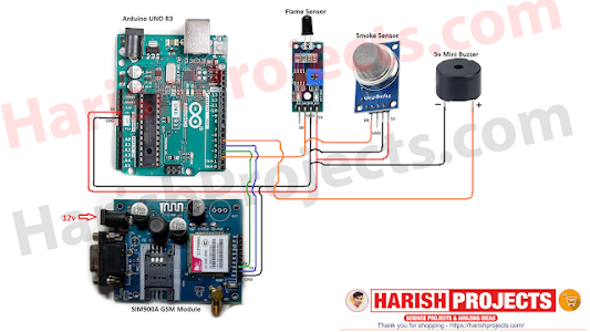
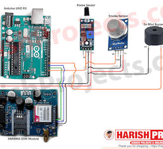
! Circuit diagram
Creating an Automatic Emergency Call & SMS System When Fire Alert using Arduino and GSM technology involves several steps, from gathering components to coding the Arduino to interact with sensors and the GSM module. Here’s a detailed process to guide you through building this project.
### Components Needed
1. Arduino Board: Arduino Uno or Nano
2. GSM Module: SIM800L or similar
3. Gas/Security Sensor: MQ-2 or another smoke sensor
4. Buzzer: To indicate alarm status
5. LEDs (optional): For visual alerts
6. Power Supply: For the Arduino and GSM module
7. Breadboard and Jumper Wires: For prototyping connections
8. Resistor: 10k ohm (for LED if used)
9. SIM Card: For the GSM module (ensure it has sufficient balance)
10. Power Supply Circuit/Regulator: If using SIM800L, it requires a suitable power supply (3.4-4.4V).
### Step-by-Step Process
#### Step 1: Design the System
1. Understand the Components:
- The MQ-2 sensor detects smoke or gas and outputs an analog signal.
- The GSM module sends SMS and makes calls based on commands it receives from the Arduino.
2. Determine System Flow:
- Sensor detects smoke → Arduino reads sensor signal → If smoke is detected, trigger SMS and emergency call → Activate buzzer/LED for local alert.
#### Step 2: Assemble the Circuit
1. Wiring the Gas Sensor:
- Connect the A0 pin of the MQ-2 sensor to Analog Pin A0 on the Arduino.
- Connect the power (VCC) and ground (GND) pins of the MQ-2 to 5V and GND on the Arduino.
2. Wiring the GSM Module:
- Connect the GSM module's TXD pin to the Arduino RX (typically pin 10).
- Connect the GSM module's RXD pin to the Arduino TX (typically pin 11).
- Provide power to the GSM module (ensure it is between 3.4V - 4.4V).
3. Connecting the Buzzer (optional):
- Connect one terminal of the buzzer to a digital pin (e.g., pin 8) and the other terminal to ground.
- If using an LED for alerting, connect it in series with a resistor to another digital pin (e.g., pin 9).
4. Breadboard Setup:
Organize the components neatly on a breadboard (optional but recommended) to make connections easier.
#### Step 3: Write the Arduino Code
1. Install the Arduino IDE:
- Make sure you have the Arduino IDE installed on your computer.
2. Program the Code:
- The code should read the MQ-2 sensor's output and check if the value exceeds a certain threshold indicating smoke presence. When it does, send an SMS and make a call using the GSM module.
Sample Code:
#include <SoftwareSerial.h> // Include the software serial library
SoftwareSerial gsm(10, 11); // RX, TX
int smokeSensorPin = A0; // MQ-2 connected to A0
int buzzerPin = 8; // Buzzer connected to digital pin 8
int ledPin = 9; // LED connected to digital pin 9
void setup() {
Serial.begin(9600); // Start serial communication for debug
gsm.begin(9600); // Start GSM serial communication
pinMode(buzzerPin, OUTPUT);
pinMode(ledPin, OUTPUT);
digitalWrite(buzzerPin, LOW); // Turn off buzzer initially
digitalWrite(ledPin, LOW); // Turn off LED initially
}
void loop() {
int smokeLevel = analogRead(smokeSensorPin); // Read the smoke level
Serial.println(smokeLevel); // Print smoke level for debugging
if (smokeLevel > 400) { // Threshold value for smoke detection
emergencyAlert();
} else {
digitalWrite(buzzerPin, LOW); // Turn off buzzer and LED if no smoke
digitalWrite(ledPin, LOW);
}
delay(1000); // Wait for a second before next reading
}
void emergencyAlert() {
digitalWrite(buzzerPin, HIGH); // Turn on buzzer
digitalWrite(ledPin, HIGH); // Turn on LED
// Send SMS
gsm.println("AT+CMGF=1"); // Set SMS mode
delay(100);
gsm.println("AT+CMGS=\"+1234567890\""); // Replace with your phone number
delay(100);
gsm.print("Fire Alert: Smoke detected!"); // SMS text
delay(100);
gsm.write(26); // Send SMS (CTRL+Z)
delay(100);
// Make call
gsm.println("ATD+1234567890;"); // Replace with your phone number
delay(10000); // Wait for 10 seconds for the call
gsm.println("ATH"); // Hang up call
}
```
3. Upload the Code:
- Connect the Arduino to your computer via USB and upload the code using the Arduino IDE.
#### Step 4: Testing the System
1. Power Up the System:
- Connect the Arduino to the power supply and ensure all components are correctly powered.
2. Simulate a Fire Situation:
- Use something like a lighter or a match (do this carefully and safely) near the MQ-2 sensor to produce smoke and test the alert functionalities.
3. Check Alerts:
- Ensure that the system sends the SMS and makes a call as expected when smoke is detected. Observe the buzzer and LED operation as well.
4. Adjust Thresholds:
- Modify the threshold in the code if necessary based on testing results to ensure optimal performance.
#### Step 5: Final Assembly and Safety Considerations
1. Secure the Components:
- Once testing is complete and the device functions correctly, secure all components in a suitable enclosure to ensure durability and safety.
2. Place the System:
- Choose a strategic location for placing the sensor where it can effectively detect smoke (such as near kitchens or heating appliances).
3. Regular Maintenance:
- Regularly check the sensor and GSM module to ensure they are functioning properly and replace the SIM card if necessary.
### Conclusion
By following these steps, you will have successfully created an automated fire alert system that can effectively notify you through calls and SMS in the event of smoke detection. This GSM-based project showcases practical applications of Arduino in improving safety measures.
If you have any specific questions or need additional assistance with certain parts of the process, feel free to ask!