
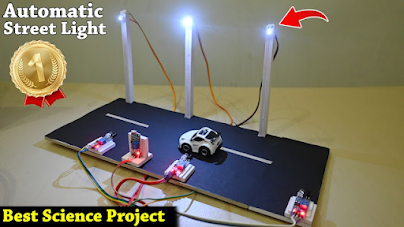
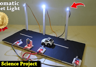
Automatic Smart Street Light | Best science Project | Harish Projects
### Description: Automatic Smart Street Light | Best Science Project | Harish Projects Introducing the **Automatic Smart Street Light**, an innovative and efficient solution designed to enhance urban lighting systems by integrating advanced technology with practical applications. This project, developed by Harish Projects, showcases how modern technology can be harnessed to conserve energy, improve safety, and reduce costs in street lighting. **Why an Automatic Smart Street Light?** Traditional street lighting systems are often inefficient, operating continuously regardless of ambient light conditions or pedestrian activity. The Automatic Smart Street Light addresses these issues by utilizing light sensors and motion detection to adjust the brightness of the lights based on real-time conditions. This smart system not only conserves energy by turning off or dimming lights when they're not needed but also provides brighter illumination in areas with high pedestrian traffic, enhancing safety and visibility for both pedestrians and drivers. **What Will You Learn?** Through this project, you'll gain hands-on experience and insights into the following key components: - **Components Needed**: A comprehensive list including Arduino or Raspberry Pi, light sensors, PIR motion sensors, LED street lights, and relay modules. - **Wiring and Circuit Design**: Detailed instructions and circuit diagrams to guide you in assembling the components for optimal functionality. - **Programming the Microcontroller**: Step-by-step instructions on writing the code that enables the system to detect light levels and motion, allowing dynamic control of the street lights. - **Real-World Application**: Discussion on how this project can be implemented in real-world scenarios, promoting energy efficiency and smart city initiatives. **Features of the Automatic Smart Street Light**: - **Light Detection**: Automatically turns on/off based on ambient light conditions. - **Motion Sensitivity**: Increases brightness when detecting movement, ensuring safety in public spaces. - **Energy Efficiency**: Achieves significant energy savings compared to traditional streetlights. - **User-Friendly**: Simple interface and operation for easy implementation and maintenance. This smart street light project is an ideal science fair entry or academic project, demonstrating the intersection of technology, sustainability, and smart city infrastructure. Join us as we delve into this exciting project, showcasing how innovation can create a safer, more energy-efficient environment for our communities! --- Feel free to modify any part of this description to suit your style or specific focus! If you need additional help or information, just let me know!
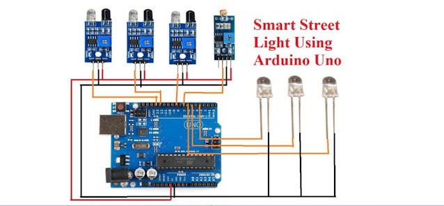
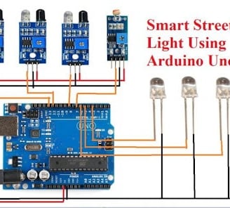
# circuit diagram
Creating an Automatic Smart Street Light system involves several steps, from gathering the necessary components to programming the microcontroller. Here’s a detailed guide to help you build this project from start to finish.
### Components Needed
1. Microcontroller: Arduino Uno or Raspberry Pi
2. Light Sensor: LDR (Light Dependent Resistor) or a photoresistor
3. Motion Sensor: PIR (Passive Infrared) sensor
4. Relay Module: To control the LED lights
5. LED Street Light: High-power LED or an array of LED lights
6. Resistors: For circuitry (e.g., 10k ohm for LDR)
7. Breadboard/Wiring: For prototyping connections
8. Jumper Wires: For making connections
9. Power Supply: Appropriate power source for the Arduino and LEDs (battery or adapter)
10. Enclosure: To house the components and protect them from environmental factors
### Step-by-Step Process
#### Step 1: Design the System
1. Understand the Workflow:
- The system will automatically turn on the street light when ambient light is low and increase its brightness when motion is detected (e.g., passing pedestrians or vehicles).
2. Plan the Circuit:
- Decide on the placement of the sensors and lights. The LDR should be positioned to accurately detect surrounding light levels, while the PIR sensor should be aimed at areas with expected movement.
#### Step 2: Assemble the Circuit
1. Wiring the Light Sensor (LDR):
- Connect the LDR in a voltage divider configuration:
- One terminal of the LDR connects to 5V.
- The other terminal connects to an analog input pin (e.g., A0) on the Arduino and a resistor (e.g., 10k ohm) to ground.
2. Wiring the Motion Sensor (PIR):
- Connect the PIR sensor:
- Connect the VCC pin to 5V.
- Connect the GND pin to ground.
- Connect the OUT pin to a digital input pin (e.g., pin 2) on the Arduino.
3. Wiring the Relay Module:
- Connect the relay to control the LED lights:
- Connect the signal pin of the relay to a digital output pin (e.g., pin 3) on the Arduino.
- Connect the VCC and GND of the relay to 5V and ground.
4. Connecting the LED Lights:
- Wire the LED lights to the relay according to the relay’s specifications, ensuring it can safely handle the voltage and current.
#### Step 3: Write the Arduino Code
1. Install the Arduino IDE:
- If you haven't already, download and install the Arduino IDE.
2. Program the Code:
- Write the code to read values from the LDR and PIR sensors to control the operation of the street lights. Below is a sample code snippet:
```cpp
// Pin assignments
const int ldrPin = A0; // LDR sensor pin
const int pirPin = 2; // PIR sensor pin
const int relayPin = 3; // Relay pin
void setup() {
pinMode(relayPin, OUTPUT);
pinMode(pirPin, INPUT);
digitalWrite(relayPin, LOW); // Ensure relay is off initially
Serial.begin(9600);
}
void loop() {
int ldrValue = analogRead(ldrPin); // Read LDR value
int pirValue = digitalRead(pirPin); // Read PIR status
Serial.println(ldrValue); // Print LDR value for debugging
// Check ambient light level and PIR status
if (ldrValue < 500) { // Adjust threshold based on testing
if (pirValue == HIGH) {
digitalWrite(relayPin, HIGH); // Turn on light
} else {
digitalWrite(relayPin, LOW); // Keep light off if no motion
}
} else {
digitalWrite(relayPin, LOW); // Turn off light if it's bright
}
delay(1000); // Delay for stability
}
```
3. Upload the Code:
- Connect the Arduino to your computer and upload the code via the Arduino IDE.
#### Step 4: Testing the System
1. Power the System:
- Connect the power supply to the Arduino and the relay module.
2. Simulate Conditions:
- Test the system by covering the LDR to simulate low light conditions and moving in front of the PIR sensor to see if the street light turns on appropriately.
3. Adjust Sensitivity and Thresholds:
- Monitor and adjust the thresholds in the code based on your testing results and the environment to ensure optimal performance.
#### Step 5: Final Assembly and Deployment
1. Secure the Components:
- Once testing is complete, secure all components in a suitable enclosure to protect them from weather conditions.
2. Install the System:
- Place the smart street light system in a designated area where it can effectively monitor ambient light and movement.
3. Regular Maintenance:
- Periodically check the system to ensure all components are functioning properly and to adjust settings as necessary based on changes in the environment.
### Conclusion
By following these steps, you've successfully created an Automatic Smart Street Light that not only saves energy but also enhances safety in public spaces. This project demonstrates the practical applications of Arduino for smart city solutions and paves the way for further enhancements, such as remote monitoring or integration with other smart systems.
If you have any questions or need further guidance on specific aspects of the project, feel free to ask!