
How to Make a Bluetooth Controlled Robot Arm with Arduino
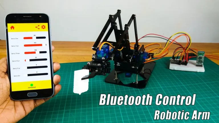
**Bluetooth Controlled Robot Arm** This project builds a robotic arm controlled wirelessly using Bluetooth. An Arduino microcontroller receives commands from a Bluetooth-enabled device (e.g., smartphone), and then drives servos to control the arm's movements (e.g., up/down, left/right, grip). This project explores robotics, electronics, and wireless communication.
SCIENCE PROJECTS
Project Overview
In this project, you will construct a robotic arm that can be controlled via a Bluetooth connection using a smartphone app. The arm will be equipped with four SG90 servo motors, allowing for a range of motion. The HC-05 Bluetooth module will facilitate communication between the Arduino and the mobile device.
Required Components
Robot Arm Kit: A pre-assembled or DIY robotic arm kit.
Arduino Nano Board: The microcontroller that will control the servos.
Servo Motors (SG90): Four servo motors to provide movement.
HC-05 Bluetooth Module: For Bluetooth communication.
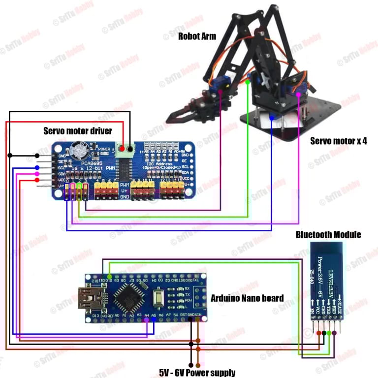
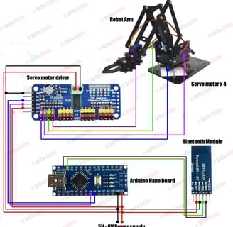
PWM Servo Motor Driver: To control the servo motors.
Breadboard: For easy connections.
Jumper Wires: For wiring connections.
Step-by-Step Instructions
Step 1: Identify the Components
Begin by gathering all the required components. Familiarize yourself with each part to understand its role in the project.
Step 2: Assemble the Robot Arm
Assemble the robotic arm kit according to the provided instructions. Ensure all joints are secure and that the servo motors are attached correctly to allow for smooth movement.
Step 3: Connect Servo Motors to the PWM Driver
Connect the four servo motors to the PWM servo motor driver. The driver will manage the power and signals sent to the motors, allowing for precise control.
Step 4: Set Up the Arduino and Bluetooth Module
Place the Arduino Nano and the HC-05 Bluetooth module on the breadboard.
Connect the components as follows:
HC-05 Connections:
VCC to Arduino 5V
GND to Arduino GND
TX to Arduino digital pin (e.g., D10)
RX to Arduino digital pin (e.g., D11)
PWM Driver Connections: Connect the PWM driver to the appropriate pins on the Arduino according to the driver’s specifications.
Step 5: Upload the Arduino Code
Connect the Arduino Nano to your computer via USB.
Open the Arduino IDE and upload the following code:
cpp
#include <Wire.h>
#include <Adafruit_PWMServoDriver.h>
#include <SoftwareSerial.h>
Adafruit_PWMServoDriver srituhobby = Adafruit_PWMServoDriver();
SoftwareSerial getValue(10, 11); // RX, TX
#define servo1 0
#define servo2 1
#define servo3 2
#define servo4 3
int S1curntPos = 350; // Current position for servo 1
int S2curntPos = 450; // Current position for servo 2
int S3curntPos = 400; // Current position for servo 3
int S4curntPos = 350; // Current position for servo 4
void setup() {
Serial.begin(9600);
getValue.begin(9600);
srituhobby.begin();
srituhobby.setPWMFreq(60); // Set frequency to 60 Hz
srituhobby.setPWM(servo1, 0, S1curntPos);
srituhobby.setPWM(servo2, 0, S2curntPos);
srituhobby.setPWM(servo3, 0, S3curntPos);
srituhobby.setPWM(servo4, 0, S4curntPos);
delay(3000);
}
void loop() {
robotArm();
}
void robotArm() {
if (getValue.available() > 0) {
String value = getValue.readString();
if (value.startsWith("S1")) {
moveServo(value, S1curntPos, servo1);
} else if (value.startsWith("S2")) {
moveServo(value, S2curntPos, servo2);
} else if (value.startsWith("S3")) {
moveServo(value, S3curntPos, servo3);
} else if (value.startsWith("S4")) {
moveServo(value, S4curntPos, servo4);
}
}
}
void moveServo(String value, int ¤tPos, int servoIndex) {
value = value.substring(3, value.length());
int newPos = value.toInt();
newPos = map(newPos, 0, 180, 150, 600);
int delta