
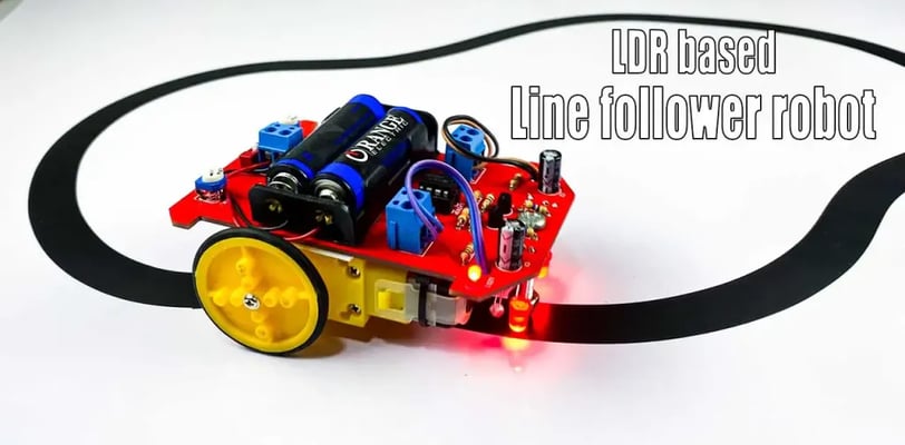
How to make a line follower robot without a development board | LDR based line follower robot
This blog post provides a tutorial on building a line-following robot using only LDR (Light Dependent Resistor) sensors, eliminating the need for a microcontroller development board. It's a more complex, analog approach compared to microcontroller-based methods, requiring a deeper understanding of electronics.
SCIENCE PROJECTS
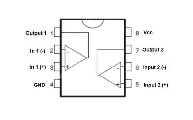
Features of LM393:
* Wide Single−Supply Range: 2.0 Vdc to 36 Vdc
* Split−Supply Range: ±1.0 Vdc to ±18 Vdc
* Very Low Current Drain Independent of Supply Voltage: 0.4 mA
* Low Input Bias Current: 25 nA
* Low Input Offset Current: 5.0 nA
* Input Common Mode Range to Ground Level
* Differential Input Voltage Range Equal to Power Supply Voltage
* Output Voltage Compatible with DTL, ECL, TTL, MOS, and CMOS Logic Levels
* ESD Clamps on the Inputs Increase the Ruggedness of the Device without Affecting Performance
* NCV Prefix for Automotive and Other Applications Requiring Unique Site and Control Change Requirements; AEC−Q100 Qualified and PPAP Capable
* These Devices are Pb−Free, Halogen Free/BFR Free, and are RoHS Compliant
Required Components:
* LDR x 2
* 5mm LED x 2
* 10k Preset x 2
* DIP switch x 1
* Two-pin terminal x 3
* IC base 8 pin x 1
* LM393 voltage dual comparator x 1
* 47 ohm Resistor x 4
* 33k ohm Resistor x 2
* 1k ohm Resistor x 2
* 10 ohm Resistor x 2
* S8550 Transistor x 2
* 100µF capacitor x 2
* 3mm LED x 2
* AA battery holder x 1
* Nut and bolt
* Gear motor x 2
* TT motor wheel x 2
OK, let's do this project step by step.
Creating a line-following robot using only LDRs (Light Dependent Resistors) and avoiding a microcontroller like an Arduino requires a more analog approach. This means using comparators and possibly op-amps to process the LDR signals and control motors. It's significantly more complex than using a microcontroller.
Here's a high-level overview, assuming you have some electronics experience:
1. Sensors: Use at least two LDRs, positioned to sense the line. The closer they are to the line, the more sensitive it will be.
2. Signal Conditioning: The LDRs' resistance changes with light. You'll need to convert this resistance change into a usable voltage signal. This usually involves using the LDRs as part of a voltage divider circuit.
3. Comparators: Comparators compare the voltage from each LDR. If one LDR senses the line (lower resistance, higher voltage), its comparator output will be high; otherwise, it's low.
4. Motor Control: The comparator outputs will drive the motors. This could involve using transistors (like a Darlington pair or MOSFETs) as switches to control the direction and speed of the motors. You'll likely need a simple H-bridge circuit to reverse motor direction.
5. Power Supply: Provide a suitable power supply for the LDRs, comparators, and motors.
Challenges:
* Precise Line Following: Achieving accurate line following without a microcontroller's sophisticated control algorithms will be difficult. The robot will likely be less precise and more prone to errors.
* Calibration: You'll need careful calibration to set the threshold voltages for the comparators.
* Complexity: The circuitry will be more complex than a microcontroller-based solution.
* Limited Functionality: You'll have very limited options for adding features.
Do you have experience with analog electronics (op-amps, comparators, transistors, H-bridges)? Knowing your experience level will help me provide more specific guidance. If you're new to electronics, a microcontroller-based approach is strongly recommended for its simplicity and ease of programming.
### Abstract
This blog post provides a tutorial on building a line-following robot without using a development board, relying instead on LDR sensors. The article is part of a larger collection of science project tutorials focusing on various applications of microcontrollers and sensors, showcasing projects ranging from simple LED chasers to more complex systems like a smart dustbin and solar tracker. The overall theme emphasizes hands-on learning and innovation in STEM fields.
### Key Points
* The blog post instructs readers on how to construct a line-following robot using LDR sensors, eliminating the need for a development board.
* It's one of many tutorials on the website focused on practical science projects.
* The projects cover a wide range of complexities, from basic electronics to more sophisticated IoT applications.
* Many projects utilize readily available components like Arduino boards, Raspberry Pi, and various sensors.
* The tutorials aim to encourage learning and innovation in science and technology.
* Several projects highlighted address real-world problems, such as a smart dustbin for waste management and a river cleaning boat.
* The website offers diverse projects suitable for different skill levels and interests.
### Related Questions
* [What are the specific components and steps involved in building the LDR-based line-following robot?](#related)
* [How do the complexity and cost of these projects compare to those using development boards?](#related)
* [What are some potential future project ideas building upon the concepts and techniques demonstrated in these tutorials?](#related)