
How to make an LED ring chaser using the Attiny85 Microcontroller
This project guides you through building an LED ring chaser using an ATtiny85 microcontroller, three 74HC595 shift registers, and 24 LEDs. Five pre-designed light patterns are included, but customization is encouraged. A PCB is recommended for easier assembly, but not required. The project is beginner-friendly, combining electronics and programming.
SCIENCE PROJECTS
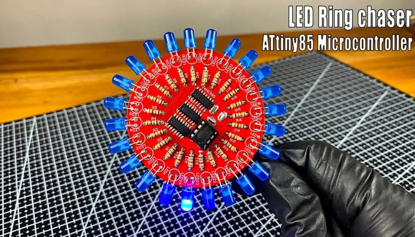
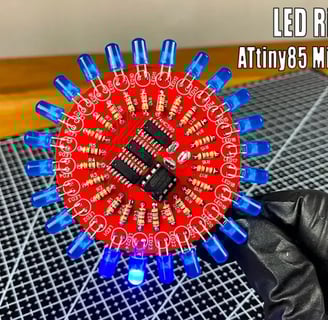
Let's build an LED ring chaser using an ATtiny85! This project is great for beginners, combining electronics and programming in a fun way. We'll use three 74HC595 shift registers to control 24 LEDs, creating dynamic light patterns. I've pre-designed five patterns, but you can easily customize them. For easier assembly, I've also created a PCB (using JLCPCB), but you can certainly wire it up without one. Programming is done via an Arduino IDE (using any Arduino board, like an UNO, as a programmer). Let's get started!
Here's what you'll need:
1 x ATtiny85 Microcontroller
24 x LEDs
24 x 180-ohm Resistors
3 x 74HC595 Shift Registers
1 x 8-Pin IC Socket
1 x DC Power Barrel Jack
This code creates a program for an LED ring chaser using an ATtiny85 microcontroller, three 74HC595 shift registers, and 24 LEDs. The code defines six different LED patterns. Let's break down the process:
1. Hardware Setup:
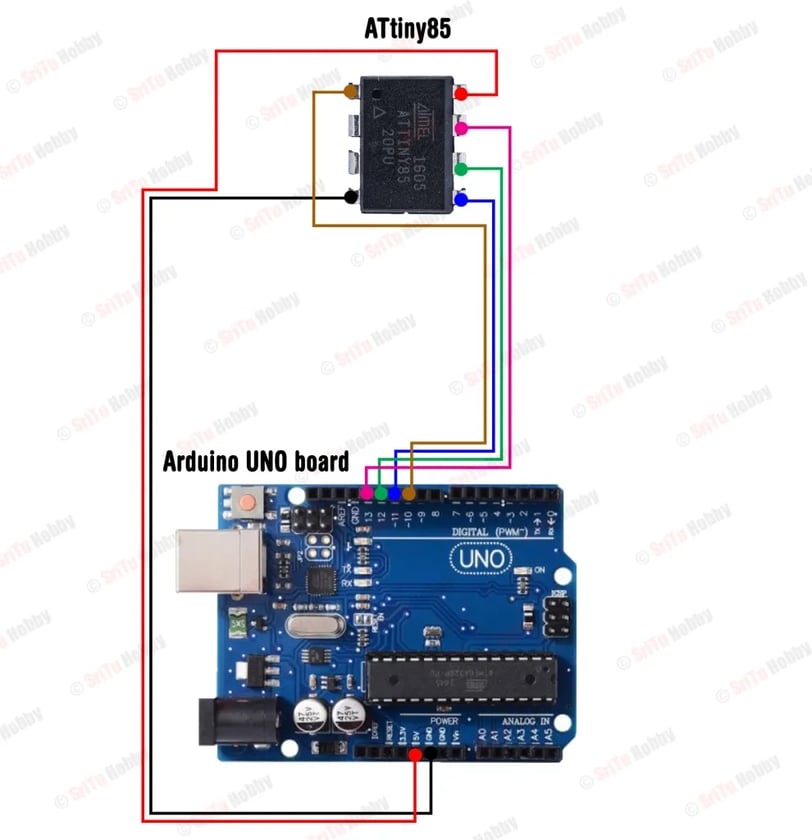
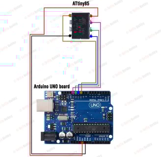
* Connections: You'll need to connect the ATtiny85's pins (1, 2, and 3, as defined in `ShiftRegister74HC595<3> led(1, 2, 3);`) to the data, clock, and latch pins of the 74HC595 shift registers respectively. The shift registers then control the 24 LEDs, each with its own 180-ohm resistor. A detailed circuit diagram is crucial for correct wiring and should be consulted. The power supply connects to the circuit.
* Components: Ensure you have all components (ATtiny85, 24 LEDs, 24 resistors, 3 74HC595s, 8-pin IC socket, DC power barrel jack).
2. Software Setup:
* Library: You need the `ShiftRegister74HC595.h` library installed in your Arduino IDE.
* Code Upload: Upload the provided code to the ATtiny85 using the Arduino IDE. You'll need to select the correct board and port for your ATtiny85 in the IDE.
3. Code Explanation:
* `ShiftRegister74HC595<3> led(1, 2, 3);`: This line initializes the shift register object, specifying three shift registers are used. Pins 1, 2, and 3 on the ATtiny85 are used for data, clock, and latch respectively.
* `void loop()`: This function calls six different LED patterns (`pattern1` to `pattern6`).
* `pattern1()` - `pattern6()`: These functions control the LED patterns. They use `led.setAllHigh()`, `led.setAllLow()`, and `led.set(a, HIGH/LOW)` to control individual LEDs or all LEDs simultaneously. The `delay()` function controls the speed of the patterns.
4. Potential Issues and Further Steps:
* Circuit Diagram: The provided code lacks a circuit diagram. Obtaining and carefully following a circuit diagram is essential to avoid hardware errors.
* Pin Mapping: Double-check the pin mappings between the ATtiny85, shift registers, and LEDs to ensure everything is connected correctly.
* Power Supply: Verify that your power supply can provide enough current to power all the LEDs.
* Troubleshooting: If the LEDs don't work as expected, systematically check the wiring, power supply, and code. Use a multimeter to verify the voltage and current at different points in the circuit.