
How to make an obstacle avoiding robot with three ultrasonic sensors
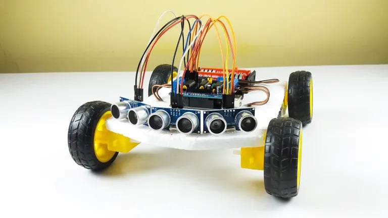
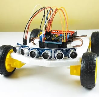
**Obstacle Avoiding Robot with Three Ultrasonic Sensors** This project builds a robot that can autonomously navigate an environment by detecting and avoiding obstacles. It utilizes three ultrasonic sensors mounted at the front and sides to sense distances. An Arduino microcontroller processes sensor data and controls the robot's movement using motors, allowing it to navigate effectively and efficiently.
SCIENCE PROJECTS
Project Overview
In this project, we will build an obstacle-avoiding robot that uses three ultrasonic sensors to detect obstacles in front, left, and right. The robot will adjust its path based on the readings from these sensors, allowing it to navigate around obstacles autonomously.
Components Needed
Arduino UNO Board: The microcontroller that will control the robot.
Three HC-SR04 Ultrasonic Sensors: For detecting obstacles.
L293D Motor Driver Shield: To control the motors.
Four DC Gear Motors: For movement.
Chassis: A robot chassis to hold all components.
Wheels: To attach to the gear motors.
Caster Wheel: For balance.
Power Supply: Battery pack to power the motors and Arduino.
Jumper Wires: For making connections.
Breadboard (optional): For additional connections.
Step-by-Step Instructions
1. Assemble the Robot Chassis
Attach the four DC gear motors to the chassis.
Fix the wheels onto the motors and attach a caster wheel for balance.
2. Wiring the Ultrasonic Sensors
Front Ultrasonic Sensor:
VCC to Arduino 5V
GND to Arduino GND
Trig to digital pin (e.g., D2)
Echo to digital pin (e.g., D3)
Left Ultrasonic Sensor:
VCC to Arduino 5V
GND to Arduino GND
Trig to digital pin (e.g., D4)
Echo to digital pin (e.g., D5)
Right Ultrasonic Sensor:
VCC to Arduino 5V
GND to Arduino GND
Trig to digital pin (e.g., D6)
Echo to digital pin (e.g., D7)
3. Wiring the Motor Driver
Connect the motor driver shield to the Arduino.
Connect the motors to the motor driver as follows:
Motor A (left motors): Connect to outputs 1 and 2.
Motor B (right motors): Connect to outputs 3 and 4.
Connect the power supply to the motor driver shield.

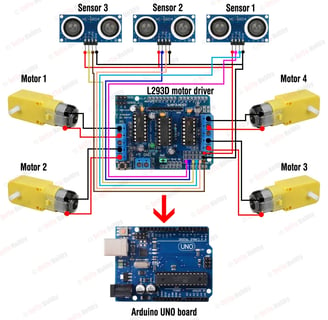
circuit diagram
4. Arduino Code
Here’s a sample code to control the robot using the three ultrasonic sensors:
cpp
// Define pins for ultrasonic sensors const int trigFront = 2; const int echoFront = 3; const int trigLeft = 4; const int echoLeft = 5; const int trigRight = 6; const int echoRight = 7; // Define motor control pins const int motorA1 = 8; // Motor A forward const int motorA2 = 9; // Motor A backward const int motorB1 = 10; // Motor B forward const int motorB2 = 11; // Motor B backward void setup() { Serial.begin(9600); // Setup ultrasonic sensor pins pinMode(trigFront, OUTPUT); pinMode(echoFront, INPUT); pinMode(trigLeft, OUTPUT); pinMode(echoLeft, INPUT); pinMode(trigRight, OUTPUT); pinMode(echoRight, INPUT); // Setup motor control pins pinMode(motorA1, OUTPUT); pinMode(motorA2, OUTPUT); pinMode(motorB1, OUTPUT); pinMode(motorB2, OUTPUT); } void loop() { long distanceFront = getDistance(trigFront, echoFront); long distanceLeft = getDistance(trigLeft, echoLeft); long distanceRight = getDistance(trigRight, echoRight); // Decision making based on sensor readings if (distanceFront < 20) { // If an obstacle is detected in front if (distanceLeft > distanceRight) { turnRight(); } else { turnLeft(); } } else { moveForward(); } delay(100); // Short delay for stability } long getDistance(int trigPin, int echoPin) { digitalWrite(trigPin, LOW); delayMicroseconds(2); digitalWrite(trigPin, HIGH); delayMicroseconds(10); digitalWrite(trigPin, LOW); long duration = pulseIn(echoPin, HIGH); return (duration / 2) * 0.0343; // Convert to cm } void moveForward() { digitalWrite(motorA1, HIGH); digitalWrite(motorA2, LOW); digitalWrite(motorB1, HIGH); digitalWrite(motorB2, LOW); } void turnLeft() { digitalWrite(motorA1, LOW); digitalWrite(motorA2, HIGH); digitalWrite(motorB1, HIGH); digitalWrite(motorB2, LOW); } void turnRight() { digitalWrite(motorA1, HIGH); digitalWrite(motorA2, LOW); digitalWrite(motorB1, LOW); digitalWrite(motorB2, HIGH); }
Explanation of the Code
Setup: Initializes the serial communication and sets up pins for the ultrasonic sensors and motors.
Loop: Continuously checks the distances from the three sensors. If an obstacle is detected in front (less than 20 cm), it decides whether to turn left or right based on which side has more space.
getDistance(): A function to measure the distance using the ultrasonic sensor.
Motor Control Functions: Functions to move forward, turn left, and turn right based on sensor readings.
5. Testing the Robot
Upload the code to the Arduino.
Power the robot with the battery pack.
Place the robot on the ground and observe its behavior. It should move forward and avoid obstacles by turning left or right based on the readings from the ultrasonic sensors.
Conclusion
This project allows you to create a more sophisticated obstacle-avoiding robot using three ultrasonic sensors, providing better navigation capabilities than a single-sensor design. You can further enhance this project by adding features like:
Speed control.
Additional sensors (like IR sensors) for better obstacle detection.
Remote control capabilities using Bluetooth or WiFi.
If you have any questions or need further details on any part of the project, feel free to ask!