
How to use a water level sensor with the Microbit board
**Water Level Sensor with Microbit** This project demonstrates how to use a water level sensor with a Microbit board. The sensor measures water depth, and the Microbit processes this data, displaying it on the LED matrix or sending it to a connected device. This project provides a foundation for building water monitoring systems, irrigation control, or flood detection applications.
SCIENCE PROJECTS
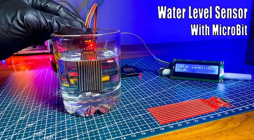
Hello and welcome back! In this tutorial, we will learn how to use a water level sensor with the Microbit board. For this project, I’ve used an LCD screen to display the water level readings and the built-in buzzer to indicate when the water level is too high. You can customize these components as needed. For example, you could replace the LCD with an LED indicator or choose a different type of component. Also, I used the Microsoft MakeCode platform for this project, which is great for beginners as it allows us to create code easily with code block-based programming. The platform also gives you the option to switch to Python or JavaScript. When you are using Python or JavaScript codes, you can see the automatically generated code blocks. Also, you can use this knowledge for small water level monitoring and leakage detection projects.
OK let’s do it step by step. The required components are given below.
Micro:bit V2 or V1 board x 1
Micro:bit sensor shield x 1
Water level sensor x 1
LCD screen x 1
I2C module x 1
Jumper wires
Keyestudio BBC Micro:bit starter kit
Using a water level sensor with a Microbit involves several steps:
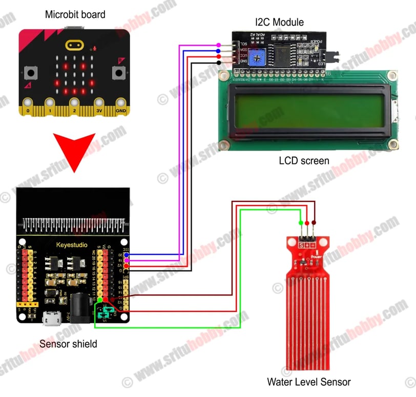
1. Wiring: Connect the water level sensor's output pin to one of the Microbit's analog pins (P0-P15). Ground the sensor's ground pin to the Microbit's ground. Power the sensor (check its specifications; it might need 3.3V or 5V) from the Microbit's 3V3 pin or an external regulated power supply.
2. Coding: Use the MicroPython or MakeCode editor for the Microbit. Read the analog value from the pin connected to the sensor. The value will change depending on the water level. A higher value generally indicates a higher water level.
3. Calibration: Test the sensor in different water levels to determine the mapping between the analog reading and the actual water level. You might need to define thresholds to indicate "high," "medium," or "low" water levels based on your calibration data.
4. Display: Use the Microbit's LEDs or an external LCD screen to display the water level readings or status (e.g., "High," "Low").
This is a simplified overview. The exact process depends on the specific water level sensor and Microbit version you are using. Consult the datasheets for both components for detailed instructions. Do you want a more detailed explanation of any of these steps, or a sample code example?
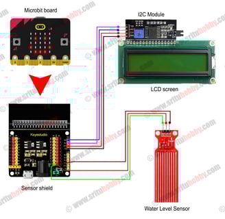
Python script and Circuit diagram
value = 0 I2C_LCD1602.lcd_init(0) I2C_LCD1602.show_string("Water Level", 0, 0) I2C_LCD1602.show_string("Monitoring", 3, 1) basic.pause(3000) I2C_LCD1602.clear() def on_forever(): global value basic.clear_screen() value = pins.analog_read_pin(AnalogReadWritePin.P10) I2C_LCD1602.show_string("Water Level:", 0, 0) I2C_LCD1602.show_string("" + str(value) + " ", 12, 0) basic.pause(100) if value > 700: I2C_LCD1602.show_string("High", 0, 1) music.ring_tone(262) elif value < 700: I2C_LCD1602.show_string("Low ", 0, 1) music.stop_all_sounds() basic.forever(on_forever)